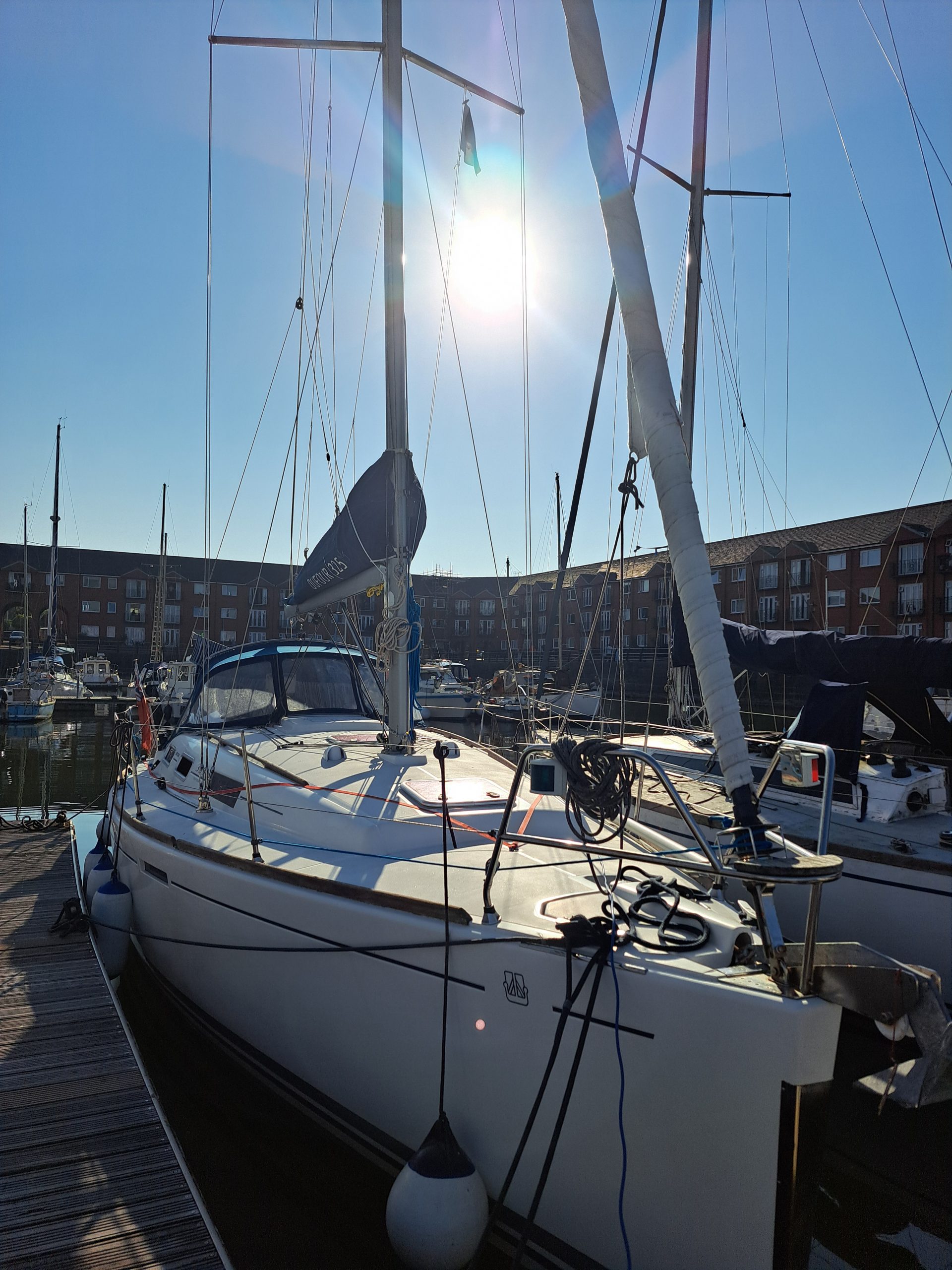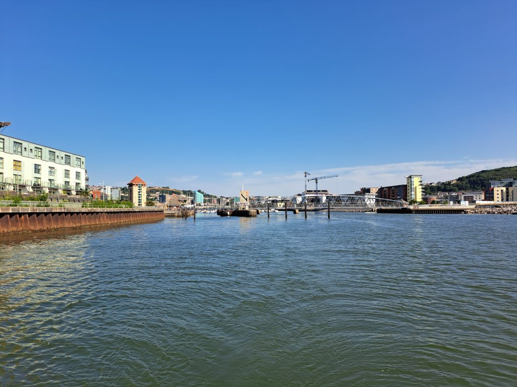

We set off at 0900 in order to get through both Swansea locks and out of the docks by 1000. High water at Swansea was at 0836, and so after punching the tide for the rest of the morning, we planned to pick up the flood tide around Nash Point.
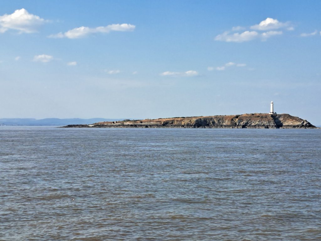
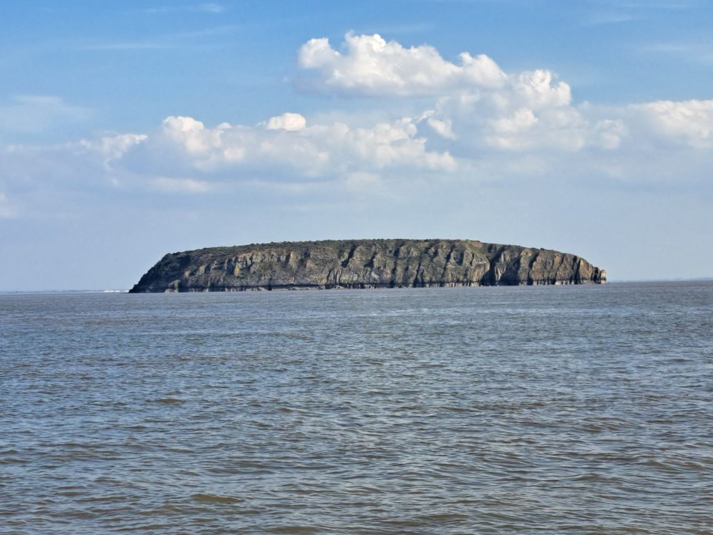
The tide today was vast – at Port of Bristol it was LW 0.96m and HW 13.24m (12.28m range). This resulted in a very high tide speed, giving us 8 knots at Barry, 10 knots between the Holms islands, and not much less all the way up to Portishead! So we arrived very early – our original ETA was 2130, but we got into the (slightly delayed) 1945 lock at the marina.
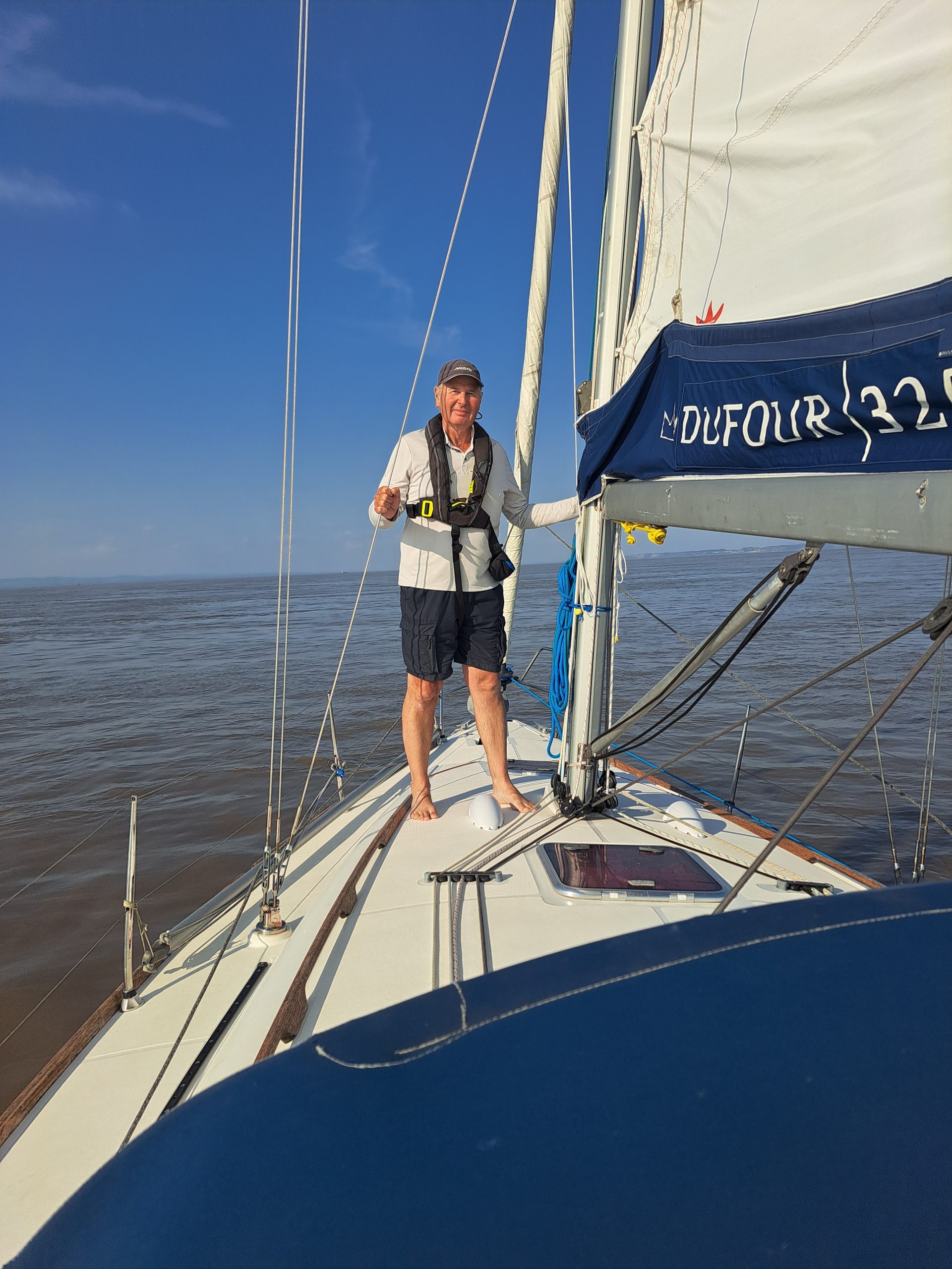
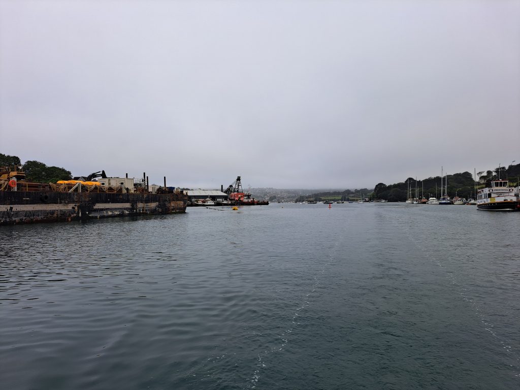
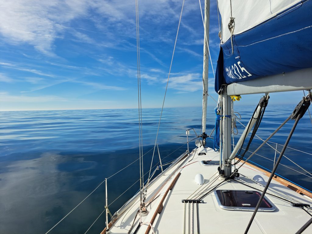
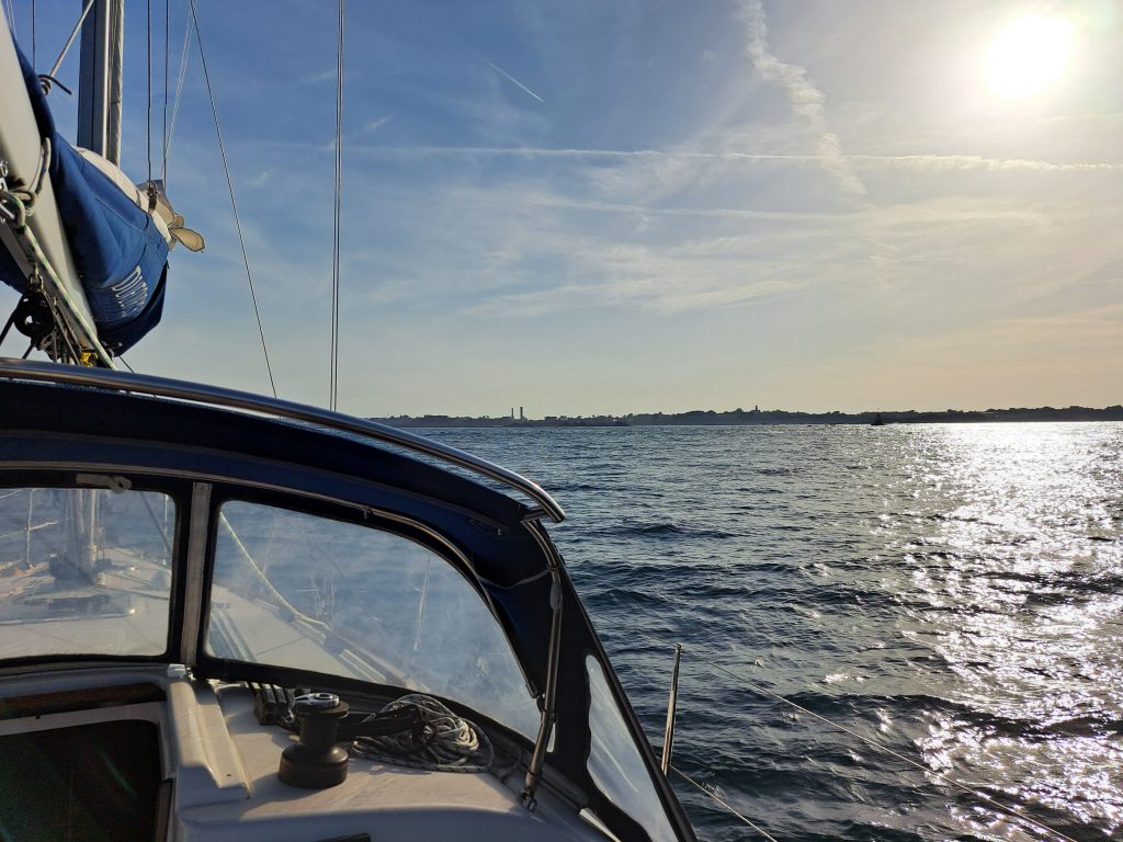
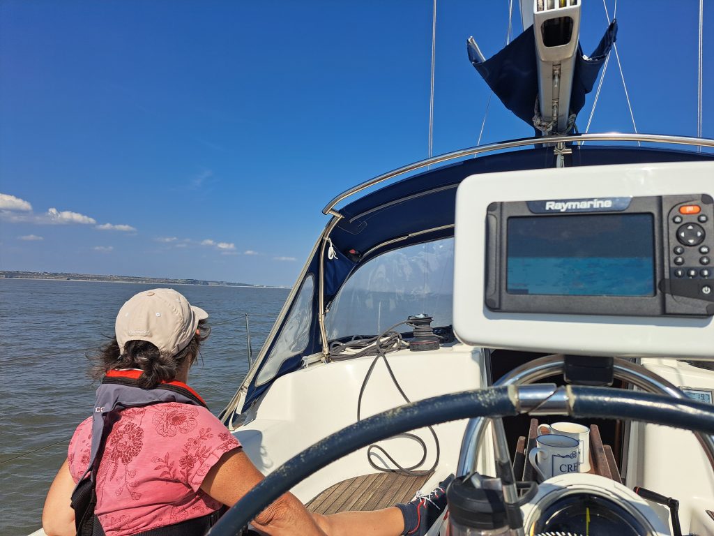
A deceptivly calm approach to Portishead – we are still doing over 9 knots across the ground!
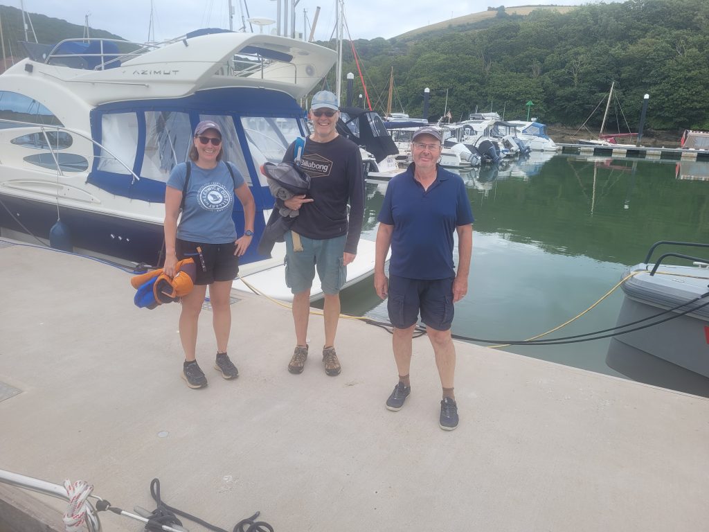
That concludes our 2026 cruise. Many thanks to everyone who joined us and visited us. We celebrated the return to our Portishead Marina mooring, with Tim and Wendy, and some drinks!